
01
What a padeye has to survive
Six failure modes, in two groups: the plate and pin around the hole, and the weld that attaches the whole thing to the structure. They fail independently, so all six get checked.
A single-plate padeye is the simplest lifting attachment there is: a plate with a hole, welded to something, with a shackle through the hole. That simplicity is why it gets designed badly. There is no obvious place for the calculation to start, so it often starts at the answer, with a plate thickness someone remembers from a previous job.
The honest starting point is the list of ways it can fail.
Around the hole, the plate can tear across its narrowest section, tear out towards the free edge, or crush locally where the pin presses on it. The pin itself can shear. Those four are geometry against material, and they are all classical mechanics that you can write out in full.
Then there is the connection to the structure. The weld group has to carry the whole load down to the base, including the part of it that is trying to bend the lug over. This is the check that governs most real padeyes, and it is the check most often done for the wrong load case.
The sixth mode is the one this article cannot help you with: the structure the lug is welded to. A perfect padeye on a shell plate that cannot take the local load is still a failed lift point. If the backing structure is a vessel wall rather than a stiff frame, the local check belongs in a different calculation entirely.
02
Getting the demand right first
Every check downstream compares against one number. Getting that number wrong makes all six checks precisely wrong together, which is the failure mode no amount of care in the checks themselves can catch.
The force at the pin is not the mass of the load. It is the tension in the leg that pulls on this particular padeye, after everything that scales it up.
Work through it in this order, and write down where each factor came from:
Share of the load. What fraction of the total mass arrives at this lift point. For a symmetric two-point lift the answer looks like half, and it is not: fabrication tolerance, centre-of-gravity uncertainty and sling length differences all mean one point takes more. Rigging practice deals with it by refusing to credit every leg with a share: a four-leg arrangement is designed as though two diagonally opposite legs carry the whole load, because that is the only distribution you can demonstrate.
Sling angle. The leg tension is the vertical share divided by the sine of the angle the leg makes with the horizontal. That relationship is mild while the legs are steep and vicious once they flatten out.
Dynamic and consequence factors. This is where discipline matters most, because it is where numbers get borrowed. A dynamic amplification factor from an offshore standard, a consequence factor for a critical lift point, a project-mandated uplift for a lift over live plant: each of these is either imposed on you by a document, or chosen by someone who has to own the choice. Write down which, for every factor you apply.
In the worked example below the design load at the pin is 250 kN, multiplied by a declared project dynamic factor of 1.15, giving an effective demand of 287.5 kN. That 1.15 is not from a standard. It is a value someone on the project decided, and the report records it as a project value rather than dressing it up as a code factor.
03
The five plate and pin checks
All five are public-domain mechanics: a force divided by an area, compared against an allowable you declare. There is nothing proprietary in any of them, which is why you can and should check them by hand.
Write for the effective demand at the pin, for the plate thickness after any corrosion allowance, for the plate width across the hole, for the hole diameter, for the pin diameter, and for the edge distance from hole centre to the free edge.
Net-section tension. The plate is trying to tear across the line through the hole, where the least material is left.
The stress is the demand divided by what is left of the section.
Net-section tension
- is the material left either side of the hole, added together
- is plate thickness after any corrosion allowance
Shear-out, sometimes called tear-out. The pin is trying to push a plug of material out towards the nearest free edge, and it does so along two planes, one either side.
Each plane is long, so the average shear stress is the demand spread over both of them.
Double-plane shear-out
- is edge distance, hole centre to the free edge
The hole radius comes off before the length is counted, which is what makes this check so much more sensitive to the edge distance than it looks.
This is the check that punishes a short edge distance, and it does so faster than intuition suggests, because the hole radius is subtracted before the length is counted. On the worked example below, taking the edge distance in by a quarter, from 80 mm to 60 mm, takes 42 percent off the resisting length.
Bearing. The pin presses on the inside of the hole over a contact patch that is genuinely small and genuinely complicated.
Engineering practice uses the projected area instead.
Pin bearing on the lug
- is the pin diameter, not the hole diameter
That is a nominal stress, not a real one, and the allowable that goes with it is correspondingly higher than a tension allowable. Comparing a nominal bearing stress against a tension allowable is a common and expensive mistake.
Pin double shear. The pin is cut across on two planes where it passes through the clevis.
Pin double shear
- is the pin's own cross-sectional area
Note that this is a check on the shackle pin, and the shackle already has a rated capacity from its manufacturer. Doing the arithmetic does not replace using the shackle inside its rating; it tells you whether the pin you actually have is consistent with the hole you drew.
Hole clearance. Not a stress check, but it belongs in the same group because it decides whether the bearing check means anything. Too tight and the shackle will not go on in the field, with gloves, in the wind. Too loose and the contact patch narrows towards a line, concentrating the real bearing stress well above the nominal value your calculation just accepted.
04
The weld group, at the angle
The weld carries three actions at once, and the third one only exists because the pin is a long way above the weld. That lever arm is what makes an off-axis sling expensive.
Take a padeye with fillet welds down each side, each of length , with leg size .
The weld group
- is throat thickness of the fillet
- is throat area of the whole group
Resolve the demand at the pin into a component along the plate and a component across it, with the leg at angle off the lug axis.
What the weld group carries
- is height from the pin centre down to the weld group centroid
That third line is the one that gets missed. The transverse component does not merely add itself to the weld stress; it acts at the end of a lever arm, and a padeye tall enough to clear a shackle bow has a lever arm of a couple of hundred millimetres. In the worked example the moment term contributes more to the weld stress than the axial term does, on a lug rigged only 15 degrees off its own axis.
The section modulus of the two-line group about its own axis, and the throat stresses that follow from it:
Throat stresses
- is the component normal to the weld's leg, direct plus bending
- is the in-plane shear component
Resolved onto the throat plane at 45 degrees those give the throat components, and the resultant is what the weld allowable is compared against. These are the engine's own symbols, so the report opens on the same notation.
A padeye checked only for load along its own plane is unchecked for the case that usually governs. And a padeye rigged at an angle out of its plane, rather than in it, is a different calculation again: the plate is bending the weak way, over a section modulus reduced by the ratio of thickness to width, which for the example below is a factor of nearly nine.
05
The worked example
A 250 kN padeye in S355, rigged 15 degrees off the lug axis. The weld governs at just over 90 percent, and every plate check has room.
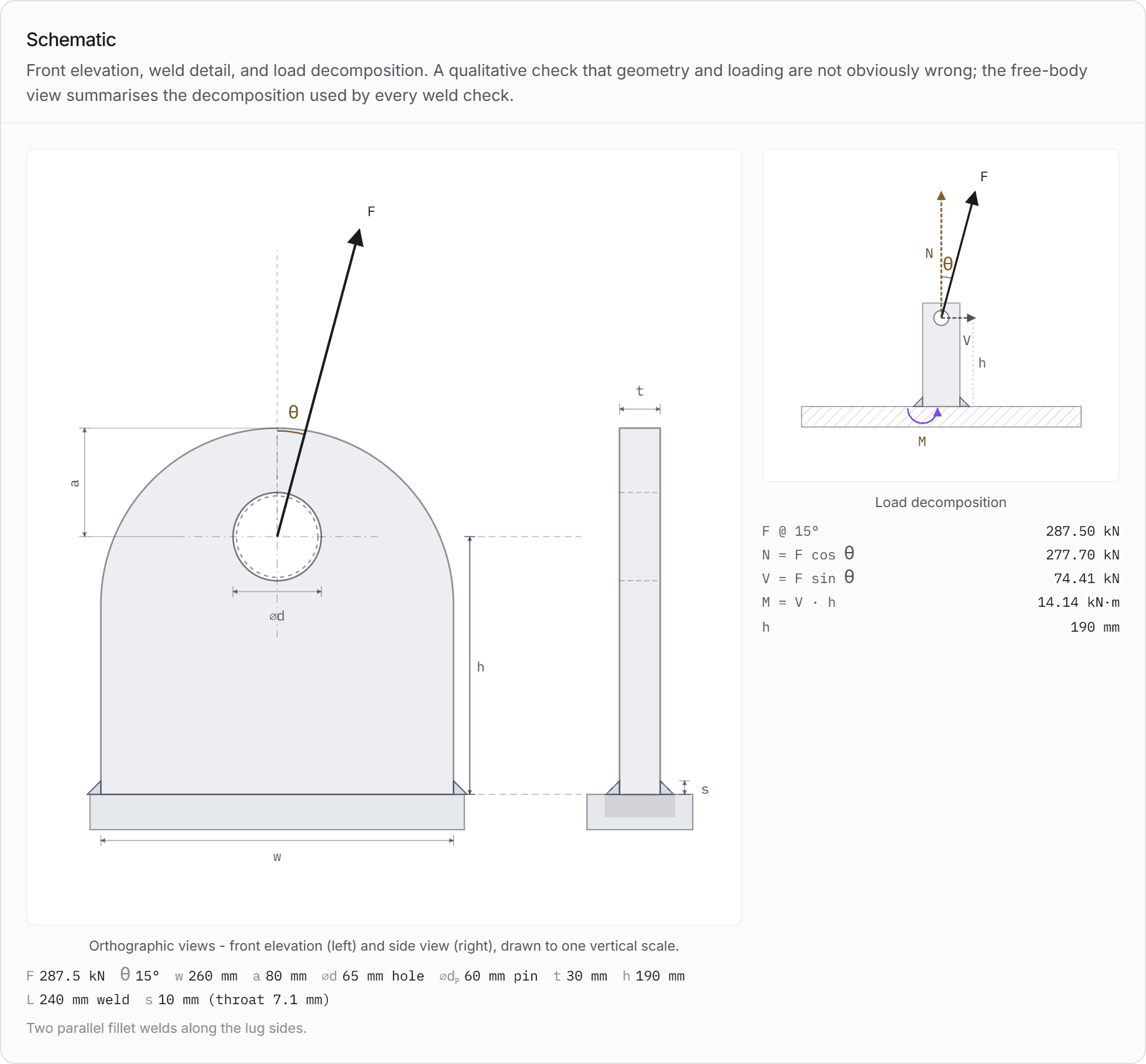
The geometry is a 30 mm plate, 260 mm wide, with a 65 mm hole for a 60 mm pin, 80 mm from hole centre to the free edge, on two 240 mm fillet welds of 10 mm leg, with the pin 190 mm above the weld group.
Lifting Lug Calculator
Full sizeOpen these inputs
Lifting Lug Calculator · computed at page render
250 kN padeye, S355, 15 degrees off axis
Public-mechanics route: classical identities against declared allowables.
| Effective demand at the pin250 kN static, dynamic factor 1.15 declared as a project value | 287.5kN |
|---|---|
| Net-section tensionF / ((w - d) t) = 287.5 kN / 5850 mm² | 49.1 / 213 MPa · 23.1% |
| Double-plane shear-outtwo planes, each (a - d/2) = 47.5 mm long | 100.9 / 123 MPa · 82.0% |
| Pin bearing on lugnominal, on the projected area d_p · t = 1800 mm² | 159.7 / 320 MPa · 49.9% |
| Pin double sheartwo planes through a 60 mm pin | 50.8 / 220 MPa · 23.1% |
| Fillet weld throat resultantthroat 7.07 mm, group area 3393.6 mm², modulus 135 744 mm³ | 187.3 / 207 MPa · 90.5% |
| Fillet weld, von Mises on the throatcombined throat stress against the tensile allowable | 265.7 / 358 MPa · 74.2% |
Allowables shown are the values declared for this example, not values any standard supplies. Change them and every utilisation moves. The engine also raises a warning on this model, and it is worth reading: a governing check above 85 percent is close enough to the limit that it should be independently verified before anyone lifts with it.
Open this example in the calculatorCheck the governing line by hand, because it is worth seeing that it is checkable.
Resolve the demand, then build the weld group:
Then the throat stresses, and the resultant the allowable is compared against:
Against the 207 MPa allowable declared for this weld.
Note what that arithmetic shows. The moment term, 104.2 MPa, is larger than the axial term, 81.8 MPa. On a lug rigged only 15 degrees off its own axis, more than half the weld stress comes from the lever arm. Design the same lug for a purely axial pull and the weld looks 41 percent utilised, which is a comfortable number that is wrong.
And this is the same run as a document. Everything above is the arithmetic; below is what somebody else receives, with the inputs it was performed on, the source each check traces to, and the assumptions stated rather than assumed.
padeye-250kn-s355-rev-A.pdf
Lifting Lug Calculator · complete, unwatermarked
Lifting Lug Calculator report
Worked example - 250 kN padeye · Rev A
2026-09-02 04:16:31 UTC
SI (mm · kN · MPa)
Mechanics of Materials (user-supplied allowables)
Inputs summary
Design load
250.00 kN
Dynamic factor
1.15
Lifting angle
15°
Plate thickness
30.0 mm
Plate width
260.0 mm
Hole diameter
65.0 mm
Pin diameter
60.0 mm
Edge distance
80.0 mm
Corrosion allow.
0.0 mm
355.0 MPa
490.0 MPa
Allow. tension
213.0 MPa
Allow. shear
123.0 MPa
Allow. bearing
320.0 MPa
Offshore
No
Weld leg
10.0 mm
Weld length × count
240.0 mm × 2
Weld allow.
207.0 MPa
Schematic
Governing summary
Governing check
Fillet weld throat resultant (mechanics)
Utilisation
0.905 (90.5%)
Overall status
pass
FEA recommended
Yes
Primary checks - Mechanics of Materials
Governing utilisation is computed from these checks only.
| Check | Demand | Capacity | U | Status |
|---|---|---|---|---|
| Net-section tension (mechanics) | 49.15 MPa | 213.00 MPa | 0.231 | Pass |
| ||||
| Double-plane shear-out (mechanics) | 100.88 MPa | 123.00 MPa | 0.820 | Pass |
| ||||
| Pin bearing on lug (mechanics) | 159.72 MPa | 320.00 MPa | 0.499 | Pass |
| ||||
| Pin double shear (mechanics) | 50.84 MPa | 220.00 MPa | 0.231 | Pass |
| Fillet weld throat resultant (mechanics) | 187.27 MPa | 207.00 MPa | 0.905 | Pass |
| ||||
| Fillet weld von Mises throat stress (mechanics) | 265.75 MPa | 358.00 MPa | 0.742 | Pass |
| ||||
| Fillet weld strength - AISC 360-22 §J2.4 | 635.52 kN | 735.07 kN | 0.865 | Pass |
| ||||
| Base section combined stress (mechanics) | - | - | - | Info |
| ||||
Cross-checks (other frameworks)
Independent utilisations from the other methodology families, shown for comparison. Not included in the governing result.
| Check | Demand | Capacity | U | Status |
|---|---|---|---|---|
| Net-section tension - BTH-1 §3-3.3.1 | 287.50 kN | 481.47 kN | 0.597 | Pass |
| Single-plane fracture - BTH-1 §3-3.3.1 | 287.50 kN | 327.00 kN | 0.879 | Pass |
| ||||
| Double-plane shear-out - BTH-1 §3-3.3.1 | 287.50 kN | 334.58 kN | 0.859 | Pass |
| Pin bearing - BTH-1 §3-3.3.4 | 287.50 kN | 266.25 kN | 1.080 | Fail |
| ||||
| Fillet weld allowable - BTH-1 §3-3.4.3 | 187.27 MPa | 80.50 MPa | 2.326 | Fail |
| ||||
| Base section interaction - BTH-1 eq (3-35) | - | - | - | Info |
| ||||
| Base section critical stress - BTH-1 eq (3-37) | - | - | - | Info |
| ||||
| Base section shear - BTH-1 eq (3-28) | - | - | - | Info |
| ||||
| Pin-plate geometry - EC3 §3.13.1 | 1.196 | 1.000 | 1.196 | Fail |
| ||||
| Pin shear - EC3 §3.13.2 | 287.50 kN | 2171.47 kN | 0.132 | Pass |
| ||||
| Plate bearing - EC3 §3.13.2 | 287.50 kN | 958.50 kN | 0.300 | Pass |
| Fillet weld - EN 1993-1-8 §4.5.3.2 directional method | 265.75 MPa | 435.56 MPa | 0.610 | Pass |
| ||||
| Fillet weld - EN 1993-1-8 §4.5.3.3 simplified method | 1324.01 N/mm | 1777.88 N/mm | 0.745 | Pass |
| ||||
| Base section yield criterion - EN 1993-1-1 eq (6.1) | - | - | - | Info |
| ||||
| Dynamic amplification factor - DNV-ST-N001 §16 | 1.100× | - | - | Info |
| ||||
| Skew-load factor - DNV-ST-N001 §16 | 1.100× | - | - | Info |
| ||||
| Lift-point consequence factor - DNV-ST-N001 §16.8.3 | 1.300× | - | - | Info |
| ||||
Weld group - demand, section, and throat stresses
Lifting load at angle (in-plane) is decomposed at the weld centroid into a normal component , a transverse shear , and an in-plane bending moment , where is the pin-to-weld centroid distance. Topology: parallel side welds (two line welds along the lug sides).
| Demand decomposition | ||
|---|---|---|
| Quantity | Symbol | Value |
| Lifting angle | 15.0° | |
| Lever arm | 190.0 mm | |
| Applied load | 287.50 kN | |
| Normal component | 277.70 kN | |
| Transverse shear | 74.41 kN | |
| Bending moment | 14.138 kN·m | |
| Section properties | ||
|---|---|---|
| Quantity | Symbol | Value |
| Leg size | 10.0 mm | |
| Throat | 7.1 mm | |
| Total weld length | 480.0 mm | |
| Throat area | 3394 mm² | |
| Section modulus | 135744 mm³ | |
| Throat stresses | ||
|---|---|---|
| Quantity | Symbol | Value |
| Normal (⊥) | 131.51 MPa | |
| Transverse shear | 131.51 MPa | |
| Longitudinal shear | 21.93 MPa | |
| Equivalent (vM) | 265.75 MPa | |
| Resultant |R| | 187.27 MPa | |
Allow. shear (τ)
207.0 MPa
Allow. tension (σ)
358.0 MPa
483.0 MPa
Awaiting source / out of scope
| Check | Demand | Capacity | U | Status |
|---|---|---|---|---|
| Pin bending - EC3 §3.13.2 | - | - | - | Awaiting source |
| ||||
| Pin combined shear + bending - EC3 §3.13.2 | - | - | - | Awaiting source |
| ||||
Warnings & scope flags
- Governing utilisation is 90.5% - at this level the result should be independently verified, including FEA where appropriate.
Assumptions
- Geometry is a single-plate lug / padeye without cheek plates. Cheek-plate configurations are out of scope for v1 and require detailed analysis.
- The pin-region checks (net section, shear-out, bearing, pin) take the full load resultant, which is conservative for the membrane load path. When an out-of-plane load direction is declared, the out-of-plane component is checked separately at the base section and weld group; without it, the load is assumed in the plane of the lug.
- Behaviour assumed linear-elastic, isotropic, homogeneous. No plastic redistribution, residual stresses, or fatigue effects are considered.
- Load line passes through the hole centre. Eccentricities between sling and lug centreline are not explicitly evaluated.
- Allowable stresses are supplied by the user. The app does NOT apply any code-specific allowable factor (ASME BTH-1 , Eurocode , DNV DAF, etc.) until the corresponding source clause has been supplied and validated.
- Pin-to-hole fit is assumed reasonable (pin diameter slightly less than hole diameter). Extreme clearances or wear are not modelled.
- Bearing stress is taken as the projected nominal value ; actual contact stress peaks are not resolved.
- Fillet welds are symmetric about the load line. The weld group is analysed with , , (in-plane), plus - when an out-of-plane load direction is declared - and resisted by the line method about the weld group's longitudinal axis. Root components combine vectorially before the throat decomposition (, ). Asymmetric weld runs remain out of scope.
Source traceability
- MECH_NET_SECTIONMechanics of Materials - net-section tensionAverage tensile stress on the net cross-section through the pin hole: . Classical identity; no code-specific allowable applied.
- MECH_DOUBLE_SHEAR_OUTMechanics of Materials - double-plane shear-outAverage shear stress on two tear-out planes between hole and free edge: , where . Classical identity; no code-specific allowable applied.
- MECH_BEARINGMechanics of Materials - bearing stressNominal bearing stress on the projected pin-on-plate area: . Classical identity; no code-specific allowable applied.
- MECH_PIN_SHEARMechanics of Materials - pin double shearAverage shear stress on two pin cross-sections (single-lug in clevis): . Classical identity; no code-specific allowable applied.
- MECH_FILLET_WELD_THROATMechanics of Materials - fillet weld throat resultantResultant throat stress on a fillet weld group with angle-aware demand decomposition , , . Root components and give throat components and ; is compared to the user-supplied shear allowable. No or electrode-specific factor applied.
- MECH_FILLET_WELD_VMMechanics of Materials - von Mises throat stressCombined throat stress for a fillet weld group using the von Mises equivalent , compared to the user-supplied tensile allowable (falls back to ).
- AISC_WELD_J24AISC 360-22 §J2.4 · 2022 · §J2.4, Eq. J2-5 (directional strength increase)Nominal fillet-weld strength per unit throat area , where is the angle between the line of action of the force resultant and the weld longitudinal axis. ASD safety factor per §B3.2.
- MECH_BASE_SECTIONMechanics of Materials - cantilever base sectionThe lug is a rectangular cantilever plate fixed at the base section, loaded at the pin a lever arm above it. Load decomposition , ; base actions , , , , ; section , , . Classical identities; the mechanics check compares the combined von Mises stress against the user-supplied allowable.
- BTH1_NET_TENSIONASME BTH-1-2020 §3-3.3.1 · 2020 · §3-3.3.1 (eqs 3-45 through 3-48)Static strength of pin-connected plate - tension on the effective net area either side of the pin hole, with reduction for pin/hole clearance and . Allowable includes design factor per §3-1.3.
- BTH1_DESIGN_FACTORASME BTH-1-2020 §3-1.3 · 2020 · §3-1.3Design factor : for Design Category A, for Design Category B. Applied to all §3-3 allowables.
- BTH1_FRACTUREASME BTH-1-2020 §3-3.3.1 · 2020 · §3-3.3.1 (eq 3-49)Single-plane fracture strength beyond the pin hole: , with measured from the hole centre to the plate edge in the direction of the applied load.
- BTH1_SHEAR_OUTASME BTH-1-2020 §3-3.3.1 · 2020 · §3-3.3.1 (eqs 3-50 through 3-52)Double-plane shear-out strength: , with and allowable .
- BTH1_BEARINGASME BTH-1-2020 §3-3.3.4 · 2020 · §3-3.3.4 (eqs 3-53 / 3-54)Pin bearing strength on the lug plate. Static bearing allowable ; rotating (Service Class ) reduced to .
- BTH1_WELDASME BTH-1-2020 §3-3.4.3 · 2020 · §3-3.4.3 (eq 3-55)Allowable fillet-weld shear on the effective throat . Extended to combined in-plane loading by comparing the resultant throat stress against the clause allowable.
- BTH1_TENSION_BENDINGASME BTH-1-2020 §3-2.4(c) · 2020 · §3-2.4(c) (eq 3-35), with §3-2.1 (eq 3-1) for Combined axial tension and biaxial bending: , with on the gross section. Reduces to the §3-2.3.5 biaxial criterion (eq 3-26) when .
- BTH1_RECT_MAJORASME BTH-1-2020 §3-2.3.3 · 2020 · §3-2.3.3 (eqs 3-19 through 3-24)Major-axis bending of solid rectangular bars, banded by : → ; → ; → . braced, else . Page-verified 2026-08-12.
- BTH1_RECT_MINORASME BTH-1-2020 §3-2.3.4 · 2020 · §3-2.3.4 (eq 3-25)Minor-axis bending of solid rectangular sections: .
- BTH1_MATERIAL_CONSTANTSASME BTH-1-2020 §1-6.1 · 2020 · §1-6.1Material constants used by the standard's member equations: MPa, MPa.
- BTH1_CRITICAL_STRESSASME BTH-1-2020 §3-2.5 · 2020 · §3-2.5 (eq 3-37)Combined normal and shear stresses at a point: . At the lug base corner (free surface).
- BTH1_PLATE_SHEARASME BTH-1-2020 §3-2.3.6 · 2020 · §3-2.3.6 (eq 3-28)Average shear stress on bars, pins, and plates: , valid for where is the clear plate depth parallel to the applied shear. Beyond that limit the clause requires a buckling method with the §3-1.3 design factor - the check reports indeterminate rather than a number.
- EC3_PIN_GEOMETRYEN 1993-1-8:2005 §3.13.1 · 2005 · §3.13.1, Table 3.9 (Type A - given thickness)Geometric requirements for pin-connected plates, Type A (given thickness ): and , where and are measured from the edge of the hole to the plate end / side edge. The Type B (given geometry) alternative , applies only to the specific lug shape drawn in Table 3.9 and is reported informatively.
- EC3_PIN_SHEAREN 1993-1-8:2005 §3.13.2 · 2005 · §3.13.2, Table 3.10 (shear)Pin shear resistance per plane: . A single-lug / clevis assembly presents two shear planes.
- EC3_PLATE_BEARINGEN 1993-1-8:2005 §3.13.2 · 2005 · §3.13.2, Table 3.10 (bearing)Pin/plate bearing resistance: .
- EC3_WELD_DIRECTIONALEN 1993-1-8:2005 §4.5.3.2 · 2005 · §4.5.3.2 (directional method)Directional check for a fillet weld throat. Two criteria: and . Correlation factor taken from Table 4.1 based on the weaker joined steel grade.
- EC3_WELD_SIMPLIFIEDEN 1993-1-8:2005 §4.5.3.3 · 2005 · §4.5.3.3 (simplified method)Simplified check on the weld throat as a vector shear: with . Conservative relative to the directional method; shown as a cross-check.
- EC3_BASE_YIELDEN 1993-1-1:2005 §6.2.1(5) · 2005 · §6.2.1(5), eq (6.1)Elastic yield criterion at a critical point; with : . Applied at the lug base section extreme fibre.
- DNV_N001_DAFDNV-ST-N001 §16.2.5 · 2018, amended 2020-01 · §16.2.5, Table 16-1 (DAF in air, excluding elevated jackups)Dynamic amplification factor from Table 16-1 by environment column and static hook load. For t: onshore , inshore , offshore ; banded constants above 100 t. Items lighter than 3 t are taken as 3 t (note 1). SHL includes rigging weight - the app approximates SHL with the design load; user-overridable.
- DNV_N001_SKEWDNV-ST-N001 §16.2.6 · 2018, amended 2020-01 · §16.2.6 (skew load factor)Skew-load factor for rigging tolerance / force-distribution effects. §16.2.6.9 permits for statically determinate lifts; the default 1.10 is retained as a conservative baseline for a single-lug padeye. Multi-sling redistribution is out of scope for v1.
- DNV_N001_CONSEQUENCEDNV-ST-N001 §16.8.3 · 2018, amended 2020-01 · §16.8.3, Table 16-5 (consequence factors)Consequence factor applied to lift points including their attachments to the structure: per Table 16-5, applied together with all relevant §16.2 factors per §16.8.4.1. Members directly supporting or framing into the lift points use (out of scope for this single-lug check set).
Code-specific allowables remain user-supplied unless the corresponding standard clause has been validated.
06
Where the allowable comes from
Nowhere, until you decide. This is the part of padeye design that no calculation can supply, and the part that decides whether the calculation means anything.
Every number in the right-hand column of that table is a value someone declared. The mechanics gives you the demand; the acceptance is a judgement that belongs to a design basis.
Three routes are common, and they are genuinely different rather than three dialects of the same thing.
A below-the-hook device standard. In the United States, a lifting device below the hook is designed to ASME BTH-1 and operated under ASME B30.20. BTH-1 works through a design factor tied to a design category, and a service class tied to expected load cycles, so the allowable is derived rather than chosen. Note the edition: BTH-1-2023 is current, and Xarpis implements the 2020 edition, which the report states on every result rather than leaving you to find out.
A structural code. In Europe a padeye welded to a structure is checked with the pin-connection rules in EN 1993-1-8, with partial factors whose recommended values are subject to national choice. This matters more than it sounds: which value of a partial factor applies is decided by your country's National Annex, not by the standard alone.
Marine warranty factors on top. An offshore lift usually takes its demand-side factors from DNV-ST-N001 and then applies a structural code for resistance.
What none of these routes will do is let you keep an allowable you cannot justify. If a value came from a spreadsheet inherited from a colleague, its provenance is your responsibility now, not theirs.
07
Seven ways this goes wrong
Every one of these has been found in a padeye that had already been calculated and signed. They are not arithmetic errors; they are modelling errors that arithmetic cannot catch.
1. The weld checked for an axial pull only. The single most common defect, and the worked example shows why: the moment from the lever arm can be the larger term even at a modest angle.
2. Bearing compared against a tension allowable. The bearing stress is nominal, computed on a projected area that does not exist. It goes with a bearing allowable, which is higher. Mixing them makes a plate look overstressed and invites someone to thicken it for no reason.
3. Edge distance measured to the wrong thing. Shear-out resistance is measured from the hole to the free edge along the load path, not to the nearest edge in general and not to the plate corner.
4. The lug designed for the sling angle on the drawing. The drawing shows the arrangement at the start of the lift. Padeye load direction changes during an upend, during a tail-out, and any time the load swings. The governing angle is the worst one in the whole operation, not the one in the elevation.
5. Out-of-plane load treated as in-plane. A lug loaded across its plate is bending about its weak axis, over a section modulus smaller by roughly the ratio of thickness to width. For the example above that is a factor of nearly nine. Lugs are not designed for out-of-plane load; they are protected from it by the rigging, and if the rigging cannot promise that, the lug is the wrong attachment.
6. Cheek plates assumed to fix everything. Cheek plates increase the bearing area at the hole. They do little for shear-out beyond their own extent, nothing for the main plate's net section outside them, and they add two welds that have to be developed to work at all.
7. The structure behind the lug never checked. A padeye is a load-introduction detail. On a stiff frame that is uninteresting. On a vessel shell it is the governing calculation, and it belongs to a different method entirely.
Common questions
- What thickness should a lifting lug be?
- Thickness is an output, not a starting point. It is set by whichever of bearing, net-section tension and shear-out governs at your design load, and then usually by the cheek-plate decision and the weld it has to develop. Start from the pin and hole you are actually rigging to, run the five plate checks, and let the governing one size the plate. A lug picked by thickness first is a lug that has to be justified backwards.
- Does the sling angle change the padeye design?
- Yes, in two separate ways, and the second is the one that gets missed. An off-vertical sling raises the force in the leg itself, and it also splits that force into a component along the plate and a component across it - the transverse component is what puts bending into the weld group through the lever arm from the pin to the weld. A padeye checked only for load along its own plane is unchecked for the case that usually governs the weld.
- Do I need a cheek plate?
- Only when bearing or net-section governs and adding thickness locally is cheaper than thickening the main plate. Cheek plates earn their place by increasing the bearing area at the hole; they do nothing for shear-out beyond the plates' own extent, and they add two more welds that must themselves be developed. If bearing is not close to governing, a cheek plate is decoration with an inspection cost.
- Which standard applies to a padeye?
- It depends on what the padeye is attached to, not on the padeye. A lifting device below the hook in the US is ASME BTH-1 territory, used alongside ASME B30.20. A padeye welded to a structure in Europe is checked with EN 1993-1-8 pin-connection rules. An offshore lift is usually driven by DNV-ST-N001 factors on the demand side regardless of which resistance code you then apply. The geometry is the same in all three; the factors and the acceptance are not.
Sources
Every document below is linked at its publisher or regulator. Xarpis reproduces no standard text; where a clause is named, the identifier is given so you can find it in your own copy.
ASME BTH-1Design of Below-the-Hook Lifting Devices
ASME · paid document
Structural, mechanical and electrical design criteria for below-the-hook lifting devices, used alongside ASME B30.20 which carries the safety requirements. The current edition is BTH-1-2023; Xarpis implements the 2020 edition and says so on every result.
EN EurocodesEurocodes: Building the future
European Commission, Joint Research Centre · free portal
The Commission's own Eurocodes portal: the structure of EN 1990 to EN 1999, the database of Nationally Determined Parameters, and the second-generation timetable. The standards themselves are sold by the national bodies, but the NDP database is free and is what decides which partial factors apply in your country.
DNV-ST-N001Marine operations and marine warranty
DNV · paid document
The marine warranty standard behind most offshore lift factor sets: dynamic amplification, skew load and consequence factors, and the load cases a marine operation is planned against. Widely applied onshore by contract even though its scope is marine.
29 CFR 1926.251Rigging equipment for material handling
US Occupational Safety and Health Administration · free to read
Inspection and safe-use requirements for chain, wire rope, fibre rope, synthetic webbing, shackles and hooks on US construction sites, including the requirement that rigging be inspected before each shift.
Run the check properly
Reading about a calculation is not the same as being able to hand one over. These tools produce the traceable record.
Something here wrong, or thinner than it should be? Tell us which paragraph and it gets rewritten. Articles carry the date they were last revised for exactly this reason.