
01
What the weld group actually carries
Three things at once, from one force: an axial term, a shear term, and a moment from the lever arm between the pin and the weld. The third is usually the largest and it is the one that is invisible on the drawing.
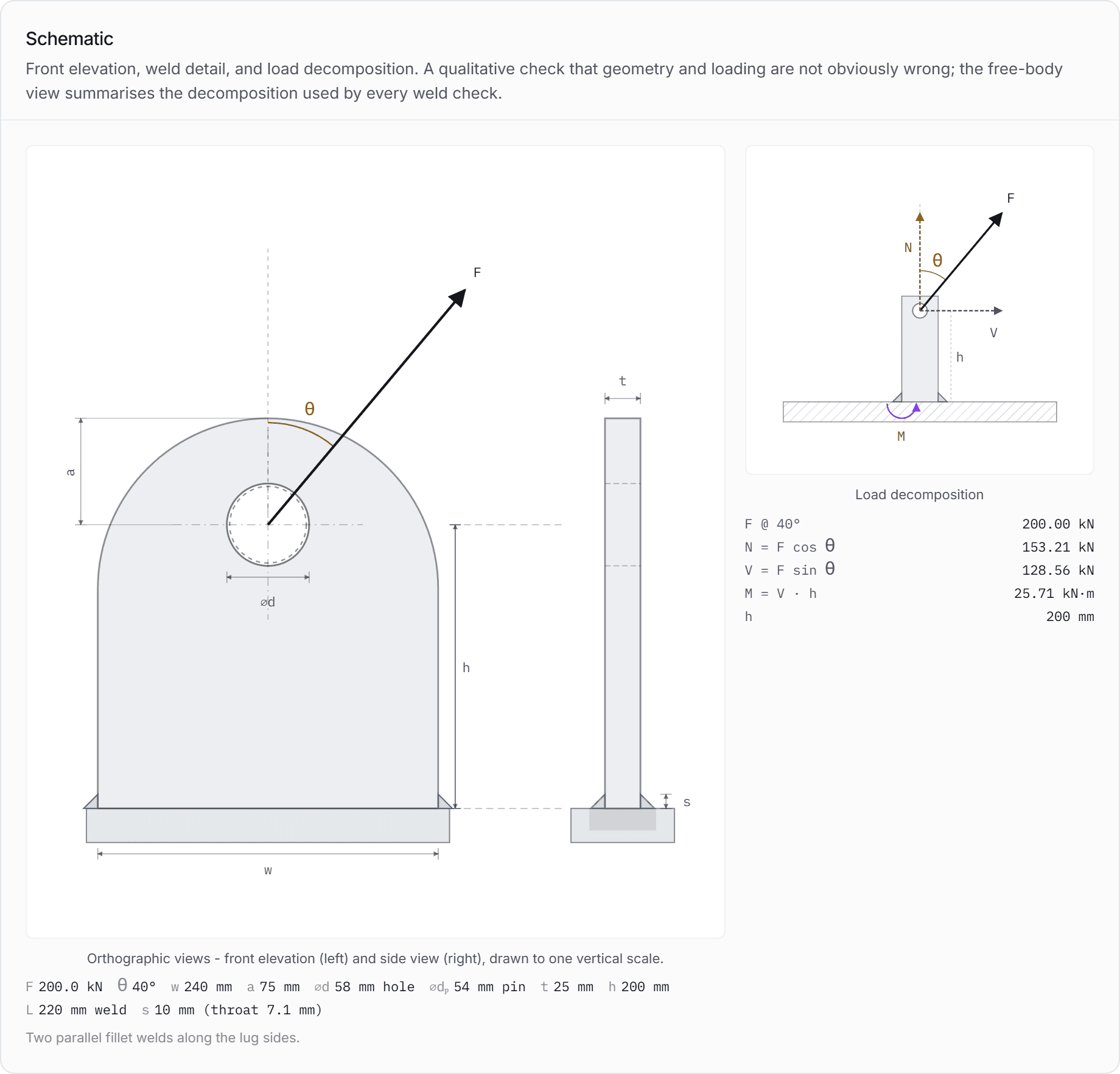
Take the force in the sling at the pin and resolve it in the plate's own coordinates.
- Along the plate's axis is a force that presses the lug into its parent structure, or pulls it away from it. Call it N.
- Across the plate's axis, in its plane is a force that tries to slide the lug sideways. Call it V.
- The lever arm is the height of the pin above the weld group's centroid. Call it h.
The transverse force , acting at height , is a moment into the weld group. Nothing else creates it, and nothing about the weld can resist it except its own section modulus.
That is why a padeye weld behaves like a moment connection. It has direct stress from N spread over the weld's throat area, a bending stress from M distributed over its section modulus, and a shear stress from V. On any lug tall enough to fit a shackle, the bending term wins.
02
The arithmetic, written out
Every step is classical mechanics on a fillet weld throat. There is nothing proprietary in it, which means you can check the engine's answer with a pencil, and you should.
Take the worked example at 20 degrees off the plate axis: a 200 kN sling force on a lug whose pin sits 200 mm above two 10 mm fillet welds, each 220 mm long.
Step one: resolve the force.
Step two: the lever arm gives the moment.
The transverse component acts at the pin, so it reaches the weld group multiplied by the height between them.
Step three: the weld group's own properties.
A fillet weld's throat is its leg size divided by the square root of two, and the two runs are treated as thin rectangles bending about their own centroid.
Step four: stress on the throat plane.
Note the two terms against each other while they are in front of you: the bending term is roughly twice the direct one, on a completely ordinary lug at a modest angle.
Step five: resolve onto the throat, and combine.
That stress acts on the weld's leg, and the throat sits at 45 degrees to it, so it resolves into equal normal and shear components on the throat plane: 127.5 MPa each. The in-plane shear from V is separate, at 22.0 MPa along the weld.
The resultant on the throat is the root of the sum of their squares: 181.7 MPa, against a declared allowable of 207 MPa. That is 87.8 percent.
Lifting Lug Calculator · computed at page render
The weld at 20 degrees off the plate axis
The case worked by hand above. The prose above and the table below are the same computation, so they cannot disagree.
| Force along the plate axis | 187.9kN |
|---|---|
| Force across the plate axis | 68.4kN |
| Lever arm, pin to weld | 200mm |
| Moment into the weld group | 13.68kN·m |
| Throat thickness10 mm leg divided by root two | 7.07mm |
| Throat area | 3111mm² |
| Section modulus | 114063mm³ |
| Resultant throat stress | 181.7MPa |
| Weld throat resultant check | 87.8% |
| Double-plane shear-out, for comparisonthe plate is not the problem | 70.7% |
The allowable is a declared value, not a code-derived one. Where a project route applies, the allowable comes from that route's rules and the engine says so on the result.
Open this example in the calculator03
The angle, and how fast it costs
Not linearly. The transverse component grows with the sine of the angle, the moment grows with it, and the direct term barely falls, so the resultant climbs faster than the angle does.
The same lug and the same 200 kN, at three angles:
Lifting Lug Calculator
Full sizeOpen these inputs
| Off the plate axis | Transverse force | Moment | Weld utilisation |
|---|---|---|---|
| 0 degrees | 0.0 kN | 0.00 kN·m | 31.1% |
| 20 degrees | 68.4 kN | 13.68 kN·m | 87.8% |
| 40 degrees | 128.6 kN | 25.71 kN·m | 134.2% |
At a straight pull the weld is at 31.1 percent and is not even the governing check: the plate's shear-out is, at 70.7 percent. Twenty degrees off axis and the weld is at 87.8 percent and governing. Forty degrees and it has failed at 134.2 percent.
The plate checks do not move - and that is the model, not the plate. Shear-out reads 70.7 percent at all three angles, and the engine is explicit about why:
Double-plane shear-out, at 20 degrees off axis
Full resultant applied conservatively - not projected by lifting angle (). Edge distance is the vertical distance to the top free edge regardless of load direction.
Read that carefully, because it cuts both ways. The full resultant is applied rather than a component of it, which is conservative on the force. The edge distance is the vertical one regardless of where the pull is going, which is a simplification: a real off-axis pull leans towards one edge, and the resisting length in that direction is not the one the check used. On this lug it does not change the conclusion, because the weld moves so far so fast that it governs long before the plate detail could matter. On a lug with a short edge distance on the side the sling leans towards, it is a question to ask separately.
Two practical consequences follow, and both are about who decides the angle.
The angle is a rigging decision, made after the padeye is designed. Somebody sizes the lug for the arrangement on the drawing. Somebody else hires the slings, sets the hook height, and produces a different angle. Unless the design states a limit, nothing connects the two.
State the limit as an acceptance criterion. Not "designed for 20 degrees" in a calculation nobody reads, but "sling to arrive within 20 degrees of the plate axis" on the drawing, where a rigger can fail it.
04
Three levers, and their exchange rates
Length, height and topology, in that order. Only one of them is cheap, and it is not the one people reach for.
Lifting Lug Calculator · computed at page render
Lever one: 80 mm more weld on each side
The same lug at 20 degrees off axis, with the weld runs extended from 220 mm to 300 mm. Nothing else changes.
| Weld run length, each sideagainst 220 mm | 300mm |
|---|---|
| Section modulusagainst 114063 mm³ | 212100mm³ |
| Resultant throat stress | 110.0MPa |
| Weld throat resultant checkagainst 87.8% at 220 mm | 53.1% |
A 36 percent increase in weld length took 40 percent off the utilisation, and handed the governing check back to the plate. Section modulus goes with the square of the run length, which is why length is the cheapest lever there is.
Open this example in the calculatorLifting Lug Calculator · computed at page render
Lever two: the same lug 100 mm taller
A common and completely innocent change - the shackle grew, or the sling needed clearance - applied to the 20 degree case with everything else identical.
| Pin height above the weldagainst 200 mm | 300mm |
|---|---|
| Moment into the weld groupagainst 13.68 kN·m | 20.52kN·m |
| Weld throat resultant checkagainst 87.8% at 200 mm | 116.6% |
A 50 percent taller lug failed a weld that had 12 percent of margin. Nothing about the load changed, nothing about the weld changed, and no drawing note would have flagged it.
Open this example in the calculatorLifting Lug Calculator · computed at page render
Lever three: welded all round instead of two runs
The same 20 degree case with the weld returned across the ends, so the group has a genuinely closed perimeter.
| Weld topologyagainst two parallel runs | all round |
|---|---|
| Throat areaagainst 3111 mm² | 3464mm² |
| Weld throat resultant checkagainst 87.8% for two runs | 70.1% |
Worth about a fifth, and worth having for a second reason the number does not show: an unreturned weld end is a stress raiser at exactly the point the bending stress peaks, and it is where a fatigue crack starts.
Open this example in the calculator05
Where the allowable comes from
Not from this article, and not from the engine. A weld allowable is a route decision, and the three common routes disagree with each other by design.
The worked examples above use a declared allowable of 207 MPa on the throat, which is a starting value a user can and should replace. The three routes a real project takes are genuinely different, and knowing which one you are in settles most arguments about the number before they start.
Whichever route you take, two things stay yours: the demand, which is the arithmetic in section two, and the geometry, which is what the drawing says. No route decides those for you.
06
Seven ways a lug weld goes wrong
Six of these are geometry and one is metallurgy. None of them is an arithmetic error.
1. The weld checked in shear only. Direct force over throat area, no moment term. It understates the throat stress by a factor of three on the worked example.
2. The lever arm measured to the wrong place. The arm runs from the pin to the weld group's centroid, not to the top of the parent plate and not to the bottom of the lug.
3. The design angle assumed rather than specified. Nothing on a drawing connects the angle the calculation used to the angle the rigging produces.
4. A taller lug fitted after the check. A larger shackle, more clearance, a different sling eye. The weld is unchanged and its demand is not.
5. Leg size increased where length was needed. Throat area goes with the leg, and section modulus goes with the square of the length. On a moment-governed weld, length is the lever that works.
6. Weld ends left unreturned. The bending stress peaks at the ends of the runs, and an unreturned end puts a stress raiser exactly there.
7. An allowable borrowed from a different route. A directional-method allowable used with a simplified-method demand, or a BTH-1 allowable applied to a Eurocode calculation. Each route's numbers are internally consistent and are not interchangeable.
Common questions
- How do you calculate the weld on a lifting lug?
- Resolve the sling force into a component along the plate axis and one across it, multiply the transverse component by the height of the pin above the weld group to get a moment, then combine a direct stress of the axial force over the throat area with a bending stress of the moment over the weld group's section modulus. Resolve that onto the throat plane at 45 degrees, add the in-plane shear, and take the resultant. On the worked 200 kN lug at 20 degrees off axis, the bending term is twice the direct term.
- Why does the moment matter more than the direct force?
- Because the lever arm is large and the section modulus is small. A padeye has to be tall enough to fit a shackle, so the pin sits 150 to 300 mm above the weld, while the weld group's section modulus is only twice the throat thickness times the square of the run length over six. On the worked lug those combine to make the bending stress about double the direct stress at 20 degrees, and the ratio grows with the angle.
- Is it better to increase the weld leg or the weld length?
- Length, on any weld where the moment governs, because the section modulus goes with the square of the run length while the throat area goes only with the leg size. In the worked example, extending the runs from 220 mm to 300 mm - a 36 percent increase - took the utilisation from 88 percent to 53 percent and handed the governing check back to the plate. Increasing the leg helps the direct term and barely touches the bending term.
- Should a lug be welded all round?
- Where the detail allows it, yes, for two separate reasons. It adds throat area and section modulus, which was worth about a fifth of the utilisation in the worked example. More importantly the bending stress in a weld group peaks at the ends of the runs, and an unreturned weld end puts a geometric stress raiser at exactly that point, which is where a fatigue crack starts on a lug that is used repeatedly.
- What allowable stress should a lug weld be checked against?
- Whatever your design route gives, and the three common routes genuinely disagree. A below-the-hook device in the US derives it through a design factor tied to a design category and a service class. The European directional method resolves the throat stresses and combines them with a correlation factor for the parent steel, while the simplified method compares one resultant against a design shear strength - the two do not agree for a transversely loaded weld, which a padeye is. The US building specification allows an increase when the weld is loaded at an angle to its axis. Never mix an allowable from one route with a demand computed for another.
Sources
Every document below is linked at its publisher or regulator. Xarpis reproduces no standard text; where a clause is named, the identifier is given so you can find it in your own copy.
ASME BTH-1Design of Below-the-Hook Lifting Devices
ASME · paid document
Structural, mechanical and electrical design criteria for below-the-hook lifting devices, used alongside ASME B30.20 which carries the safety requirements. The current edition is BTH-1-2023; Xarpis implements the 2020 edition and says so on every result.
EN EurocodesEurocodes: Building the future
European Commission, Joint Research Centre · free portal
The Commission's own Eurocodes portal: the structure of EN 1990 to EN 1999, the database of Nationally Determined Parameters, and the second-generation timetable. The standards themselves are sold by the national bodies, but the NDP database is free and is what decides which partial factors apply in your country.
ANSI/AISC 360Specification for Structural Steel Buildings
American Institute of Steel Construction · free to read
The US steel design specification, in both LRFD and ASD. AISC publishes it for free download, which makes it one of the few structural standards a reader can check the same afternoon they read about it.
ASME B30.20Below-the-Hook Lifting Devices
ASME · paid document
The safety half of the US below-the-hook pair: marking, construction, installation, inspection, testing, maintenance and operation. It requires the device to have been designed to BTH-1 and then governs everything that happens afterwards, which is why citing BTH-1 alone leaves half the obligation unstated.
Run the check properly
Reading about a calculation is not the same as being able to hand one over. These tools produce the traceable record.
Something here wrong, or thinner than it should be? Tell us which paragraph and it gets rewritten. Articles carry the date they were last revised for exactly this reason.