
01
What the client is actually buying
Not arithmetic. Somebody's willingness to be accountable for a set of choices, written down in a form that survives them leaving the project.
Ask what the deliverable is on a lift engineering scope and the answer is usually a list of documents. That is the packaging. The substance is narrower and it is worth naming, because it changes what you spend time on.
A client is buying a defensible position. When something goes wrong, or an insurer asks, or a third party reviews, somebody opens a document and finds out what was assumed, what was checked, what was not, and who decided. If that document answers those questions, the engineering was delivered. If it produces numbers with no visible basis, then the engineering may well have happened and it was not delivered.
This has a practical consequence that engineers under time pressure get backwards. A calculation that is 95 percent right with its assumptions written down is a deliverable. A calculation that is exactly right with its assumptions in the author's head is not, and the second one takes longer.
02
The eight things a calculation record carries
This list does not change with the size of the job. A one-page padeye check and a 300 t upending study carry the same eight, at different lengths.
A calculation record
- 01Scope: what this document covers and what it does notOne paragraph. The most valuable paragraph in the document and the one most often missing.
- 02Load basis: where the load came from and what factors are on itWeighed, calculated, from a drawing, from a vendor. Plus the dynamic factor, the contingency and the skew allowance, each with its origin.
- 03Geometry basis: which drawing, which revision, what was measuredA dimension with no drawing reference cannot be re-checked when the drawing changes.
- 04Materials: grade, thickness, and the allowable that followsIncluding whether the allowable is from a standard, a mill certificate or a project specification.
- 05Route and edition: which design standard, which yearBecause it decides the resistance formula and the factors, and the same geometry gets different verdicts on different routes.
- 06Results, with the governing check namedEvery check, its utilisation, and which one governs. A single overall number hides the check that matters.
- 07What was not checkedExplicitly. Fatigue, buckling, the connection into the parent structure, the vessel's own shell. A reader cannot infer omissions.
- 08Who, when, and to what revisionAuthor, checker, date, revision. Unsigned calculations get re-done rather than reviewed.
Two of these deserve their own sections, because they are where deliverables actually fail review.
03
The record behind one padeye
A 210 kN lift point at 15 degrees off axis. This is the results half of a record, and the section that follows is why the results half alone is not enough.
Lifting Lug Calculator · computed at page render
Lift point LP-04, revision C
210 kN characteristic at 15 degrees off the plate axis, with a declared dynamic factor of 1.1 and an all-around fillet weld at the base.
| Design load after the declared factor | 231.0kN |
|---|---|
| Net-section tension | 22.1% |
| Double-plane shear-out | 63.9% |
| Pin bearing on the lug | 50.6% |
| Pin double shear | 25.7% |
| Fillet weld throat resultant | 56.1% |
Six results and a governing check. Useful, and on its own it is still not a deliverable, because nothing above says which route these allowables came from or what was left out.
Open this example in the calculatorAnd here is the record saying what it did not do. The engine declines the base-section combined-stress check on this input set and gives its reason:
Base section combined stress (mechanics)
Not evaluated - no out-of-plane / base-section load case is declared. Declare the out-of-plane group (angle from the plate plane and the base-to-pin lever arm) to activate this check.
That sentence is worth more to a reviewer than another passing utilisation would be. It says a check exists, it says why it did not run, and it says exactly what input would activate it. Compare that with a report that does not mention the check at all: identical appearance, entirely different information.
Everything above is still results. Here is the same run as a deliverable. Scroll it: the eight things from the previous section are all in there, in the order a reviewer reads them, and the document is the thing that gets a revision letter and a date rather than the number.
LP-04-CALC rev C.pdf
Lifting Lug Calculator · complete, unwatermarked
Lifting Lug Calculator report
Deliverables article - lift point LP-04 · Rev C
2026-09-18 03:12:50 UTC
SI (mm · kN · MPa)
Mechanics of Materials (user-supplied allowables)
Inputs summary
Design load
210.00 kN
Dynamic factor
1.10
Lifting angle
15°
Plate thickness
28.0 mm
Plate width
230.0 mm
Hole diameter
55.0 mm
Pin diameter
51.0 mm
Edge distance
80.0 mm
Corrosion allow.
0.0 mm
355.0 MPa
490.0 MPa
Allow. tension
213.0 MPa
Allow. shear
123.0 MPa
Allow. bearing
320.0 MPa
Offshore
No
Weld leg
12.0 mm
Weld length × count
210.0 mm × 2
Weld allow.
207.0 MPa
Schematic
Governing summary
Governing check
Double-plane shear-out (mechanics)
Utilisation
0.639 (63.9%)
Overall status
pass
FEA recommended
No
Primary checks - Mechanics of Materials
Governing utilisation is computed from these checks only.
| Check | Demand | Capacity | U | Status |
|---|---|---|---|---|
| Net-section tension (mechanics) | 47.14 MPa | 213.00 MPa | 0.221 | Pass |
| ||||
| Double-plane shear-out (mechanics) | 78.57 MPa | 123.00 MPa | 0.639 | Pass |
| ||||
| Pin bearing on lug (mechanics) | 161.76 MPa | 320.00 MPa | 0.506 | Pass |
| ||||
| Pin double shear (mechanics) | 56.54 MPa | 220.00 MPa | 0.257 | Pass |
| Fillet weld throat resultant (mechanics) | 116.12 MPa | 207.00 MPa | 0.561 | Pass |
| ||||
| Fillet weld von Mises throat stress (mechanics) | 164.89 MPa | 358.00 MPa | 0.461 | Pass |
| ||||
| Fillet weld strength - AISC 360-22 §J2.4 | 468.95 kN | 874.17 kN | 0.536 | Pass |
| ||||
| Base section combined stress (mechanics) | - | - | - | Info |
| ||||
Cross-checks (other frameworks)
Independent utilisations from the other methodology families, shown for comparison. Not included in the governing result.
| Check | Demand | Capacity | U | Status |
|---|---|---|---|---|
| Net-section tension - BTH-1 §3-3.3.1 | 231.00 kN | 392.83 kN | 0.588 | Pass |
| Single-plane fracture - BTH-1 §3-3.3.1 | 231.00 kN | 309.04 kN | 0.747 | Pass |
| ||||
| Double-plane shear-out - BTH-1 §3-3.3.1 | 231.00 kN | 330.55 kN | 0.699 | Pass |
| Pin bearing - BTH-1 §3-3.3.4 | 231.00 kN | 211.22 kN | 1.094 | Fail |
| ||||
| Fillet weld allowable - BTH-1 §3-3.4.3 | 116.12 MPa | 80.50 MPa | 1.443 | Fail |
| ||||
| Base section interaction - BTH-1 eq (3-35) | - | - | - | Info |
| ||||
| Base section critical stress - BTH-1 eq (3-37) | - | - | - | Info |
| ||||
| Base section shear - BTH-1 eq (3-28) | - | - | - | Info |
| ||||
| Pin-plate geometry - EC3 §3.13.1 | 0.920 | 1.000 | 0.920 | Pass |
| ||||
| Pin shear - EC3 §3.13.2 | 231.00 kN | 1568.89 kN | 0.147 | Pass |
| ||||
| Plate bearing - EC3 §3.13.2 | 231.00 kN | 760.41 kN | 0.304 | Pass |
| Fillet weld - EN 1993-1-8 §4.5.3.2 directional method | 164.89 MPa | 435.56 MPa | 0.379 | Pass |
| ||||
| Fillet weld - EN 1993-1-8 §4.5.3.3 simplified method | 985.19 N/mm | 2133.46 N/mm | 0.462 | Pass |
| ||||
| Base section yield criterion - EN 1993-1-1 eq (6.1) | - | - | - | Info |
| ||||
| Dynamic amplification factor - DNV-ST-N001 §16 | 1.100× | - | - | Info |
| ||||
| Skew-load factor - DNV-ST-N001 §16 | 1.100× | - | - | Info |
| ||||
| Lift-point consequence factor - DNV-ST-N001 §16.8.3 | 1.300× | - | - | Info |
| ||||
Weld group - demand, section, and throat stresses
Lifting load at angle (in-plane) is decomposed at the weld centroid into a normal component , a transverse shear , and an in-plane bending moment , where is the pin-to-weld centroid distance. Topology: all-around closed fillet (adds 2·t end welds).
| Demand decomposition | ||
|---|---|---|
| Quantity | Symbol | Value |
| Lifting angle | 15.0° | |
| Lever arm | 175.0 mm | |
| Applied load | 231.00 kN | |
| Normal component | 223.13 kN | |
| Transverse shear | 59.79 kN | |
| Bending moment | 10.463 kN·m | |
| Section properties | ||
|---|---|---|
| Quantity | Symbol | Value |
| Leg size | 12.0 mm | |
| Throat | 8.5 mm | |
| Total weld length | 476.0 mm | |
| Throat area | 4038 mm² | |
| Section modulus | 174601 mm³ | |
| Throat stresses | ||
|---|---|---|
| Quantity | Symbol | Value |
| Normal (⊥) | 81.44 MPa | |
| Transverse shear | 81.44 MPa | |
| Longitudinal shear | 14.80 MPa | |
| Equivalent (vM) | 164.89 MPa | |
| Resultant |R| | 116.12 MPa | |
Allow. shear (τ)
207.0 MPa
Allow. tension (σ)
358.0 MPa
483.0 MPa
Awaiting source / out of scope
| Check | Demand | Capacity | U | Status |
|---|---|---|---|---|
| Pin bending - EC3 §3.13.2 | - | - | - | Awaiting source |
| ||||
| Pin combined shear + bending - EC3 §3.13.2 | - | - | - | Awaiting source |
| ||||
Assumptions
- Geometry is a single-plate lug / padeye without cheek plates. Cheek-plate configurations are out of scope for v1 and require detailed analysis.
- The pin-region checks (net section, shear-out, bearing, pin) take the full load resultant, which is conservative for the membrane load path. When an out-of-plane load direction is declared, the out-of-plane component is checked separately at the base section and weld group; without it, the load is assumed in the plane of the lug.
- Behaviour assumed linear-elastic, isotropic, homogeneous. No plastic redistribution, residual stresses, or fatigue effects are considered.
- Load line passes through the hole centre. Eccentricities between sling and lug centreline are not explicitly evaluated.
- Allowable stresses are supplied by the user. The app does NOT apply any code-specific allowable factor (ASME BTH-1 , Eurocode , DNV DAF, etc.) until the corresponding source clause has been supplied and validated.
- Pin-to-hole fit is assumed reasonable (pin diameter slightly less than hole diameter). Extreme clearances or wear are not modelled.
- Bearing stress is taken as the projected nominal value ; actual contact stress peaks are not resolved.
- Fillet welds are symmetric about the load line. The weld group is analysed with , , (in-plane), plus - when an out-of-plane load direction is declared - and resisted by the line method about the weld group's longitudinal axis. Root components combine vectorially before the throat decomposition (, ). Asymmetric weld runs remain out of scope.
Source traceability
- MECH_NET_SECTIONMechanics of Materials - net-section tensionAverage tensile stress on the net cross-section through the pin hole: . Classical identity; no code-specific allowable applied.
- MECH_DOUBLE_SHEAR_OUTMechanics of Materials - double-plane shear-outAverage shear stress on two tear-out planes between hole and free edge: , where . Classical identity; no code-specific allowable applied.
- MECH_BEARINGMechanics of Materials - bearing stressNominal bearing stress on the projected pin-on-plate area: . Classical identity; no code-specific allowable applied.
- MECH_PIN_SHEARMechanics of Materials - pin double shearAverage shear stress on two pin cross-sections (single-lug in clevis): . Classical identity; no code-specific allowable applied.
- MECH_FILLET_WELD_THROATMechanics of Materials - fillet weld throat resultantResultant throat stress on a fillet weld group with angle-aware demand decomposition , , . Root components and give throat components and ; is compared to the user-supplied shear allowable. No or electrode-specific factor applied.
- MECH_FILLET_WELD_VMMechanics of Materials - von Mises throat stressCombined throat stress for a fillet weld group using the von Mises equivalent , compared to the user-supplied tensile allowable (falls back to ).
- AISC_WELD_J24AISC 360-22 §J2.4 · 2022 · §J2.4, Eq. J2-5 (directional strength increase)Nominal fillet-weld strength per unit throat area , where is the angle between the line of action of the force resultant and the weld longitudinal axis. ASD safety factor per §B3.2.
- MECH_BASE_SECTIONMechanics of Materials - cantilever base sectionThe lug is a rectangular cantilever plate fixed at the base section, loaded at the pin a lever arm above it. Load decomposition , ; base actions , , , , ; section , , . Classical identities; the mechanics check compares the combined von Mises stress against the user-supplied allowable.
- BTH1_NET_TENSIONASME BTH-1-2020 §3-3.3.1 · 2020 · §3-3.3.1 (eqs 3-45 through 3-48)Static strength of pin-connected plate - tension on the effective net area either side of the pin hole, with reduction for pin/hole clearance and . Allowable includes design factor per §3-1.3.
- BTH1_DESIGN_FACTORASME BTH-1-2020 §3-1.3 · 2020 · §3-1.3Design factor : for Design Category A, for Design Category B. Applied to all §3-3 allowables.
- BTH1_FRACTUREASME BTH-1-2020 §3-3.3.1 · 2020 · §3-3.3.1 (eq 3-49)Single-plane fracture strength beyond the pin hole: , with measured from the hole centre to the plate edge in the direction of the applied load.
- BTH1_SHEAR_OUTASME BTH-1-2020 §3-3.3.1 · 2020 · §3-3.3.1 (eqs 3-50 through 3-52)Double-plane shear-out strength: , with and allowable .
- BTH1_BEARINGASME BTH-1-2020 §3-3.3.4 · 2020 · §3-3.3.4 (eqs 3-53 / 3-54)Pin bearing strength on the lug plate. Static bearing allowable ; rotating (Service Class ) reduced to .
- BTH1_WELDASME BTH-1-2020 §3-3.4.3 · 2020 · §3-3.4.3 (eq 3-55)Allowable fillet-weld shear on the effective throat . Extended to combined in-plane loading by comparing the resultant throat stress against the clause allowable.
- BTH1_TENSION_BENDINGASME BTH-1-2020 §3-2.4(c) · 2020 · §3-2.4(c) (eq 3-35), with §3-2.1 (eq 3-1) for Combined axial tension and biaxial bending: , with on the gross section. Reduces to the §3-2.3.5 biaxial criterion (eq 3-26) when .
- BTH1_RECT_MAJORASME BTH-1-2020 §3-2.3.3 · 2020 · §3-2.3.3 (eqs 3-19 through 3-24)Major-axis bending of solid rectangular bars, banded by : → ; → ; → . braced, else . Page-verified 2026-08-12.
- BTH1_RECT_MINORASME BTH-1-2020 §3-2.3.4 · 2020 · §3-2.3.4 (eq 3-25)Minor-axis bending of solid rectangular sections: .
- BTH1_MATERIAL_CONSTANTSASME BTH-1-2020 §1-6.1 · 2020 · §1-6.1Material constants used by the standard's member equations: MPa, MPa.
- BTH1_CRITICAL_STRESSASME BTH-1-2020 §3-2.5 · 2020 · §3-2.5 (eq 3-37)Combined normal and shear stresses at a point: . At the lug base corner (free surface).
- BTH1_PLATE_SHEARASME BTH-1-2020 §3-2.3.6 · 2020 · §3-2.3.6 (eq 3-28)Average shear stress on bars, pins, and plates: , valid for where is the clear plate depth parallel to the applied shear. Beyond that limit the clause requires a buckling method with the §3-1.3 design factor - the check reports indeterminate rather than a number.
- EC3_PIN_GEOMETRYEN 1993-1-8:2005 §3.13.1 · 2005 · §3.13.1, Table 3.9 (Type A - given thickness)Geometric requirements for pin-connected plates, Type A (given thickness ): and , where and are measured from the edge of the hole to the plate end / side edge. The Type B (given geometry) alternative , applies only to the specific lug shape drawn in Table 3.9 and is reported informatively.
- EC3_PIN_SHEAREN 1993-1-8:2005 §3.13.2 · 2005 · §3.13.2, Table 3.10 (shear)Pin shear resistance per plane: . A single-lug / clevis assembly presents two shear planes.
- EC3_PLATE_BEARINGEN 1993-1-8:2005 §3.13.2 · 2005 · §3.13.2, Table 3.10 (bearing)Pin/plate bearing resistance: .
- EC3_WELD_DIRECTIONALEN 1993-1-8:2005 §4.5.3.2 · 2005 · §4.5.3.2 (directional method)Directional check for a fillet weld throat. Two criteria: and . Correlation factor taken from Table 4.1 based on the weaker joined steel grade.
- EC3_WELD_SIMPLIFIEDEN 1993-1-8:2005 §4.5.3.3 · 2005 · §4.5.3.3 (simplified method)Simplified check on the weld throat as a vector shear: with . Conservative relative to the directional method; shown as a cross-check.
- EC3_BASE_YIELDEN 1993-1-1:2005 §6.2.1(5) · 2005 · §6.2.1(5), eq (6.1)Elastic yield criterion at a critical point; with : . Applied at the lug base section extreme fibre.
- DNV_N001_DAFDNV-ST-N001 §16.2.5 · 2018, amended 2020-01 · §16.2.5, Table 16-1 (DAF in air, excluding elevated jackups)Dynamic amplification factor from Table 16-1 by environment column and static hook load. For t: onshore , inshore , offshore ; banded constants above 100 t. Items lighter than 3 t are taken as 3 t (note 1). SHL includes rigging weight - the app approximates SHL with the design load; user-overridable.
- DNV_N001_SKEWDNV-ST-N001 §16.2.6 · 2018, amended 2020-01 · §16.2.6 (skew load factor)Skew-load factor for rigging tolerance / force-distribution effects. §16.2.6.9 permits for statically determinate lifts; the default 1.10 is retained as a conservative baseline for a single-lug padeye. Multi-sling redistribution is out of scope for v1.
- DNV_N001_CONSEQUENCEDNV-ST-N001 §16.8.3 · 2018, amended 2020-01 · §16.8.3, Table 16-5 (consequence factors)Consequence factor applied to lift points including their attachments to the structure: per Table 16-5, applied together with all relevant §16.2 factors per §16.8.4.1. Members directly supporting or framing into the lift points use (out of scope for this single-lug check set).
Code-specific allowables remain user-supplied unless the corresponding standard clause has been validated.
04
The route is part of the deliverable
Same plate, same pin, same weld, same load. Two design routes, and one of them says this padeye is fine while the other says the weld is 44 percent over.
The table below is the same four physical checks read twice: once on the declared route with its allowables, and once on the ASME BTH-1 cross-check the engine runs alongside it.
| Physical check | Declared route | BTH-1 cross-check |
|---|---|---|
| Net-section tension | 22.1% | 58.8% |
| Double-plane shear-out | 63.9% | 69.9% |
| Pin bearing on the lug | 50.6% | 109.4% |
| Fillet weld at the base | 56.1% | 144.3% |
Nothing physical changed between those two columns. What changed is the design factor the route imposes and the basis of the allowable it compares against, and those are decisions that live in a standard rather than in the geometry.
Where the route is actually declared. It is one control, four options, and every check downstream reads from it:
Lifting Lug Calculator
Full sizeOpen these inputs
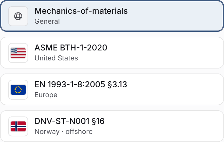
The reviewable version of this is not "we used BTH-1". It is: this project's specification requires that route, in that edition, at that design category, and here is the clause reference for the design factor. Then a reader can tell that the route was chosen before the answer rather than after it, which is the distinction that matters and the one an unlabelled results table cannot make.
05
The document set for a heavy lift
Six documents, and the relationships between them are what a reviewer actually reads.
Lift plan. The operation: sequence, equipment, positions, crew, exclusion zones, hold points, weather limits, contingency. The document that gets carried on site. It references the others rather than repeating them.
Rigging arrangement drawing. What is connected to what, with sling lengths, angles, hook heights and every accessory identified by its rating. The drawing that makes the calculation's assumptions visible to somebody holding a shackle.
Lift point calculations. Each lift point, checked, with the eight things above. Usually the largest document by page count and the one most often lifted from a previous project.
Below-the-hook device design. Where a spreader, frame or lifting beam is involved. Its own record, and it carries a marked rated capacity that appears in the rigging arrangement.
Ground bearing or foundation assessment. The crane's outrigger or track pressures against a stated allowable bearing capacity, and the mat design that gets them there. The document that most often has an owner boundary problem, because the allowable capacity belongs to the geotechnical side and the demand belongs to the lifting side.
Weight and centre of gravity report. Where the load's properties came from, with a tolerance. Everything else in the set depends on it, and it is the document most often assumed rather than produced.
The relationships a reviewer checks between them
- 01The weight in the lift plan equals the weight in the calculationsIncluding whether both are gross, and both carry the same contingency.
- 02The sling angle on the drawing equals the angle in the padeye checkThis is the single most common mismatch in a document set.
- 03The rated capacity on the device equals the one in the arrangementAnd the marking on the physical item matches both.
- 04The crane load case in the ground assessment is the governing oneNot the one somebody had a chart page for.
- 05Every document names the same revision of the same drawingTwo documents against two drawing revisions is a set that agrees with nothing.
06
Revisions, dates, and the thing that goes stale
The load. It is always the load.
A calculation is valid against the inputs it was performed with, and one of those inputs changes more often than any other: the weight of the thing being lifted. Insulation gets added, a nozzle grows, a pump is substituted, spare parts travel inside the vessel. Each of those is somebody else's ordinary change and none of them triggers a call to the lifting engineer.
Three habits deal with this, and they cost almost nothing.
State the weight the calculation was performed at, in the lift plan, in bold. Not in an appendix. The person on site is the one who can notice that the tag plate says something different.
State the margin to the next threshold. "Governing check at 64 percent, and this arrangement remains acceptable to 265 kN" tells a project manager what a change costs before they make it. A bare utilisation does not.
Re-issue rather than annotate. A revised weight is a new revision of the calculation, with the superseded revision retained. Marked-up copies with hand-written weights circulate for years and lose their marks.
07
Six ways a deliverable fails review
None of these is an arithmetic error. Every one of them is a document problem, which is why checking the maths again does not find them.
1. No scope statement. The reader cannot tell whether the parent structure was in or out, so they have to ask, and the answer arrives three weeks later.
2. The route is not named. See the table above. The number is uninterpretable without it.
3. Omissions are invisible. Fatigue was not assessed. Nothing in the document says so, so a reader who does not already know the check list assumes it was.
4. Inputs with no provenance. A 42 mm pin diameter with no drawing reference cannot be re-checked when the pin is substituted.
5. No revision control. Two versions in circulation, both undated, and the site has the older one.
6. An overall percentage instead of a check list. The single figure is always the governing one, and the value of a record is that a reader can see the ones just behind it.
Common questions
- What should a lifting calculation report contain?
- Eight things, and the list does not change with the size of the job. Scope, meaning what the document covers and what it does not. The load basis with every factor and where it came from. The geometry basis, naming the drawing and its revision. Materials and the allowables that follow. The design route and its edition. Results with the governing check named. What was not checked. And who, when, and to what revision.
- Why does the design route have to be named in the report?
- Because it decides the verdict. The worked padeye in this article governs at 64 percent on its declared route and its weld comes out at 144 percent on the below-the-hook cross-check, on identical geometry carrying an identical load. Nothing physical differs between those two columns; what differs is the design factor the route imposes and the basis of the allowable. A utilisation with no route attached cannot be interpreted at all.
- Why does a report need to say what it did not check?
- Because a missing check and a passing check are indistinguishable to a reader. If fatigue was not assessed, or the parent structure was out of scope, or the shell behind the attachment belongs to somebody else, a reader who does not already know the full check list will assume it was covered. Stating the omission takes one line and is often the most useful line in the document.
- What documents make up a heavy lift engineering package?
- Usually six: the lift plan, the rigging arrangement drawing, the lift point calculations, the below-the-hook device design where one is used, the ground bearing or foundation assessment, and the weight and centre of gravity report. What a reviewer actually reads is the relationships between them - whether the weight in the plan matches the weight in the calculations, whether the sling angle on the drawing matches the angle in the padeye check, and whether every document names the same drawing revision.
- What makes a calculation go out of date?
- The weight, almost always. Insulation gets added, a nozzle grows, a pump is substituted, spare parts travel inside the vessel, and none of those changes triggers a call to the lifting engineer. Three habits handle it: state the weight the calculation was performed at prominently in the lift plan, state the margin to the next threshold so a project manager can see what a change costs, and re-issue a revision rather than annotating a printed copy.
Sources
Every document below is linked at its publisher or regulator. Xarpis reproduces no standard text; where a clause is named, the identifier is given so you can find it in your own copy.
ASME BTH-1Design of Below-the-Hook Lifting Devices
ASME · paid document
Structural, mechanical and electrical design criteria for below-the-hook lifting devices, used alongside ASME B30.20 which carries the safety requirements. The current edition is BTH-1-2023; Xarpis implements the 2020 edition and says so on every result.
HSE lifting equipment guidanceLifting equipment at work: planning and organising lifting operations
UK Health and Safety Executive · free to read
The regulator's own plain-language account of what planning a lifting operation means in UK law: who is competent to plan it, what a plan has to address, and how it scales from a routine repetitive lift to a one-off complex one. Free, short, and the closest thing to an official answer to 'what has to be in a lift plan'.
DNV-ST-N001Marine operations and marine warranty
DNV · paid document
The marine warranty standard behind most offshore lift factor sets: dynamic amplification, skew load and consequence factors, and the load cases a marine operation is planned against. Widely applied onshore by contract even though its scope is marine.
LEEALifting Equipment Engineers Association
LEEA · free portal
The international trade association for the lifting equipment industry, and the body behind the LEEA Academy qualifications that most UK and Gulf lifting inspectors hold. Its technical library and member directory are where a reader goes to check that whoever examined their equipment is qualified to have done so.
Run the check properly
Reading about a calculation is not the same as being able to hand one over. These tools produce the traceable record.
Something here wrong, or thinner than it should be? Tell us which paragraph and it gets rewritten. Articles carry the date they were last revised for exactly this reason.